Thursday, June 4, 2009

Electric Tankless Water Heaters

Sords Electric Sell Electric Tankless Heaters.

A tankless heater heats water as it passes through the heater.  It does not store hot water like a traditional tank water heater.  The tankless heater turns on when it senses flow, heats the water and hot water flow out the outlet.  When the flow of the water stops, a flow switch detects this and the tankless heater turns off.  Tankless heaters only use electricity when they are providing hot water.  A tank heater is continually using electricity by keeping the water hot waiting for a faucet to be turned on.

There are tankless heaters designed for the whole house, just sinks or for use in industrial plants.
Industrial use tankless heaters are sometimes called inline heaters or circulation heaters.  They can be made quite large to heat large volumes of water, gases or oils.  In home or commercial use tankless heaters are smaller and require less power to operate.

Tankless heaters do have a limitation.  The limitation is the amount of flow that the heater can heat.  For example, our 17 kilowatt (kw) heater (AE115) designed to operate in a home in the southern USA, can heat a flow rate of 2.5 gpm of water, 45 degrees F.  Meaning that the water temperature will be raised 45 degrees from the inlet temperature to the outlet temperature.  At a higher flow rate the degree change will be less, and at lower flow rates the change will be greater.  The 27 kw heater (AE125) will raise the the water 45 degrees at a 4.0 gpm flow rate and 65 at the 2.5 gpm.  2.5 gpm is a standard shower flow rate.  

Both of the AE tankless heaters heaters require larger breakers in the electrical panel than a tank heater.  The AE115 requires 2 x 40 amp two pole breakers and the AE 125 requires 3 x 40 amp breakers.  Both heaters operate on 220-240 volts AC.  Also the wire gauge needs to be 8 to carry the larger amperage load.

The tankless heater will save on electrical usage since it is only heating water when it is required.  A tank heater is on for many hours a day and also on when no one is home, thus wasting electricity.  A tankless heater can use up to 1/2 the amount of power to heat your water.  Another advantage is the tankless heater takes up very little space and can be located just about anywhere in the home.

Sords Electric has electric tankless heaters for sinks, AE7.2, AE9.5 and AE12 Power Stream heaters.  These heaters draw 30, 40 and 50 amps respectively.  We also carry the AE115 and AE125 for whole house use.  The amperages are 80 and 120.  Only one shower can be run at a time but back to back showers can be run all day long.

Monday, June 1, 2009

2020

SCHNEIDER ELECTRIC ROBERTSHAW VIBRATION PRODUCTS

Robertshaw vibration switches and monitors minimize production shut down time and repair costs by measuring the total accelerated force (shock) present on a machine. Individual acceleration measurements are summed to yield the total destructive force acting on a machine. This information enables you to proactively and stategically maintain equipment. Our vibration models range from the standard traditional to new technologically enhanced models. All provide unsurpassed dependability

Robertshaw Vibration Switches and Monitors protect machinery against unnecessary shut down and repair costs, so businesses can maximize their productivity. Our wide variety of models can meet any protection need.

Typical Applications include:
Robertshaw Vibration SwitchRobertshaw Vibration SwitchRobertshaw Vibration SwitchRobertshaw Vibration SwitchRobertshaw Vibration SwitchRobertshaw Vibration Switch

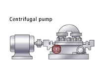
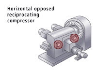
Robertshaw Vibration Instruments can be used on rotating or reciprocating machines. To select the proper instrument for your machine, follow the link to Selection Guide Matrix and/or follow the steps below.
  1. Select the unit that meets the environmental conditions that your machine is located in [hazardous area (explosion-proof or I.S.) or non-hazardous; temperature range].
  2. Select the power supply and/or remote reset voltage required.
  3. Select the unit that provides you with the required measurement type, range and frequency for your machine. The type would be acceleration (G's) or velocity (IPS). The range would be the G range or IPS range. The frequency would be in Hertz (RPM of machine ÷ 60).
  4. If you require time delays (Start, Monitor or Start & Monitor delays – see note below), select the instrument that offers that feature. Models 375A/376A series offer fixed time delays; Model 566 offers adjustable Monitor Delay; Model 563A MUST BE used with Vibraswitch Model 366 or 365, and provides adjustable time delay for the units that are connected to the 563A Monitor. If time delay is not required proceed to step 5 below.
  5. Select the function that you desire:
    1. Alarm or shut down only by:
      1. Electrical SPDT or DPDT Switch Operation (Models 365/366, Models 375A/376A with Start Delay Only).
      2. Solid State Triac Switch Operation (Models 375A/376A except for Start Delay ONLY Model which has SPDT Switch Contacts).
      3. Pneumatic Operation (Model 368).
    2. 4-20 mADC output only (Models 570B/571A).
    3. 4-20 mADC output with alarm and/or shut down contacts, triac outputs (Model 566).
  6. Check to see if the Model selected above has a mounting configuration suitable for your application. All units are surface mount except for the following:
    1. Models 570B/571A are stud mount.
    2. Model 563A Monitor is used with the surface mount 365/366 Vibraswitches to provide adjustable start and monitor time delays.
  7. After you have made your selection, review the complete Product Specification Sheet to verify your selection is correct.

    NOTE:
    Start, Monitor, or Start & Monitor Delays are used to prevent unwanted shut down or alarm during start-up or normal operation of your machine.
    1. Start Delay: Prevents unwanted shut down when excessive vibration exists (which exceeds the set-point of the vibration switch or monitor) during the start-up of the machine.
    2. Monitor Delay: Prevents unwanted shut down when short excessive vibration spikes occur (which exceed the set-point of the vibration switch or monitor) during normal operation of the machine. Spikes are typically caused by detonation, cavitation, other machinery in the immediate area, etc.
The 365A and 366 Vibraswitch malfunction detectors provide maximum protection for large motors, pumps, compressors and other rotating or reciprocating equipment by responding to mechanical malfunctions the instant they occur. The 365A is UL and c-UL certified Explosion-proof, and Type 4/4X & IP66 Weatherproof, E365A is ATEX certified,. The 366 is NEMA 4 and CSA certified.

The 375A and 376A Vibraswitches are identical to the 365/366 models, except that they incorporate built-in electronic starting, monitoring or combination starting and monitoring time delay circuits. The 375A is FM approved. The 376A has a NEMA 4 enclosure. Both require 120 VAC power.

The EURO366G Vibraswitch malfunction detector provides maximum protection from rotating and reciprocating of large motors, pumps or compressors. It is intended for indoor or outdoor use in hazardous or non-hazardous areas with ATEX and CE certifications.

The 368 pneumatically operated Vibraswitch constitutes the most effective known method of avoiding costly damage due to mechanical malfunction of rotating and reciprocating machinery where air is the operating control medium.

The 566 velocity acceleration vibration monitor employs totally solid state circuitry. Sensing mode, whether velocity or acceleration, is field selectable without loss of accuracy.

The 570B loop-powered, stud mount, vibration transmitter provides a 4-20 mADC output proportionate to vibration. This unit, known for its compact size, has a two-pin connector that mates with a splash-proof connector/cable assembly.

The 571A loop-powered, stud mount, vibration transmitter provides a 4-20 mADC output proportionate to vibration. This unit measures acceleration or velocity in three different ranges and is reverse polarity protected. It is compact in size and a 1/4-28 tapped hole and stud are provided for mounting. The two-pin connector mates with a standard MIL-C-5015 two-socket connector with a boot that provides weatherproof and splash-proof connection.


Monday, May 25, 2009

Safety Cords ~ Fire Shield Cords


Fire Shield is a next generation extension cord with built-in intelligence to sense cord damage and shut off the power before a fire can start.  No other extension cord has this capability.

Industry statistics indicate there is a cord fire approximately every 6 minutes.  The most frequent causes of such fires are short circuits, overloading, damage, and/or misuse of extension cords.

A special shield surrounds each of the insulated conductors of the Fire Shield Extension Cord.  The shield is continuously monitored by electronics in the plug head.  When a dangerous electrical condition is detected by current leaking to the shield, power is shut off before a fire can start.

Fire Shield differ from GFCI's and ground conductors. Grounded conductors only provide a path to ground. GFCI’s detect ground faults.  Neither detects the breakdown in the insulation of a standard extension cord, which can lead to an arcing condition that may start a fire.  By utilizing a sensing shield around the insulated Fire Shield conductors combined with intelligent electronics in the plug head, Fire Shield can detect damage in the cord such as series faults (broken and frayed conductors) and parallel faults (insulation damage between the live conductors), and shut off the power before a fire can start.

Unintentional misuse of extension cords is the main reason for cord fires.  Cords may be crimped, pinched, frayed, overloaded, overheated, or just worn out.  Any of these conditions can lead to an extension cord fire.  Fire Shield can detect any leakage currents from these conditions and shut off power before a fire can occur.

The cord fire protection is a function of the special shield and relates to the Fire Shield extension cord only.

Fire Shiled should be used anywhere you use standard extension cords or power strips; in children’s rooms, pet areas, with space heaters, electric blankets, waterbeds, etc.  Children and pets have been known to bite or chew electrical cords.  Fire Shield, with its built-in intelligence may provide protection in these circumstances.   Fire Shield Safety Extension Cords should also be used during the holidays with Christmas trees and other holiday decorations because of the tendency to overload extension cords.

Standard surge protectors only provide protection against power surges, which is important.  However, standard surge protectors do not provide cord fire prevention.   TRC has recently introduced a next generation line of Fire Shield Surge Protectors that not only protects against power surges, but also provides cord fire prevention.

Fire Shield cords are now required at many colleges as the only power strip allowed in college dorms.  This is due to students overloading the strips, or tacking the cords to walls or pinching the cords between doors or around corners.  All these issues can and will cause fires.

Fire Shield cords are patented and UL/CSA approved.

Sords Electric

Facebook


Saturday, May 23, 2009

Temperature Switches ~ Mechanical ~ bi-metal

Sords Electric sells Temperature Swtiches.

Temperature Switches are designed to work in two different ways, bi-metal switches and thermal expansion.
both of these methods require no electrical power for the switch to sense temperature and mechanically actuate the switch mechanism. Of course power has to b present to actually be switched.

A bi-metal switch uses two dis-similar metals. Metallic objects expand and contract when heated and cooled, by attaching or fusing or combining two different metals together, they will expand or contract, or bend or otherwise cause a movement that can be used to make a switch contact. By restricting the movement with a spring or tension, the switch can be "set' for desired temperatures. The switch can be calibrated at the factory or by the user.

A thermal expansion switch uses a liquid/gas filler that will expand and move a plunger that will actuate the switch.
A liquid is stored in the "bulb" of the switch and when heated will boil and turn to gas and expand. The expansion will move up the capillary and create pressure to actuate the switch mechanism. As with bi-metal switches these switches ca be calibrated by the users to actuate at different set points. Also, thermal expansion switches can have two or more set points by use of two or more switches.

A few examples of temperature switches that use this technology are the thermostats in cars to allow coolant to flow, and the old style round house thermostats that used bi-metal and mercury to make the switching. Most over temperature safety switches found in appliances are bi-metal switches as they can be small and inexpensive. This Style of switch is factory set to a certain temperature. Some of these switches can have a manual reset mechanism and some will reset when they cool to a lower temperature.


Wednesday, May 20, 2009

Solid State Relays ~ Fast switching

Gavazzi SSR single phase


Sords Electric sells Solid State Relays (SSR) by Carlo Gavazzi.

A Solid State relay( SSR ) is an electrical switch that opens and closes under the control of another electrical circuit. A solid state relay( SSR ) is a solid state electronic component that provides a similar function to an electromechanical relay but does not have any moving components, increasing long-term reliability. With early SSR's, the tradeoff came from the fact that every transistor has a small voltage drop across it. This voltage drop limited the amount of current a given SSR could handle. As transistors improved, higher current SSR's, able to handle 100 to 1,200 amps, have become commercially available.
Gavazzi SSR with Heatsink
A solid state contactor is a very heavy-duty solid state relay, including the necessary heat sink, used for switching electric heaters, small electric motors and lighting loads; where frequent on/off cycles are required. There are no moving parts to wear out and there is no contact bounce due to vibration. They are activated by AC control signals or DC control signals from Programmable logic controller (PLCs), PCs, Transistor-transistor logic (TTL) sources, or other microprocessor and microcontroller controls.

Solid-state relays ( SSR's ) control load currents through solid-state switches such as triacs, SCRs, or power transistors. These elements are controlled by input signals coupled to the switched devices through isolation mechanisms such as transformers, reed relays, or optoisolators. Some solid-state relays also incorporate snubber circuits or zero-crossing detectors to reduce spikes and transients generated by interrupting load current. Since semiconductor switches can dissipate significant amounts of power, solid-state relays must generally be heat sinked to minimize operating temperature.

SSRs generate heat because of the voltage drop present in all semiconductor devices. A 40-A relay, for example, typically drops 1.2 V during conduction and, thus, dissipates 50 W of heat. However, SSR heat generation generally does not require special system design. These devices usually mount on circuit boards or control panels containing other semiconductor devices. Cooling and heat-sinking methods used for these devices are likely to be adequate for the SSR.

Some SSRs designed for controlling ac loads incorporate a zero-voltage turn-on circuit that switches the load on or off only when the power-line sine wave passes through zero. Highly capacitive loads such as lamps and heaters which produce high inrush currents at turn on generate little electromagnetic interference if actuated when line voltage is zero. However, inductive loads such as motors and transformers can saturate during the first half cycle after turn on and produce maximum interference when switched on as line voltage passes through zero. Zero-voltage switches should not be used.

Carlo Gavazzi offers a comprehensive range of solid state relays (SSR’s) featuring direct copper bonding technology for increased life and reliability. SSR’s are used extensively in the plastics, packaging, food processing, and HVAC industries - primarily for temperature control. They are the logical replacement for mercury contactors.

Other applications include lighting and pump switching. Furthermore, many of our relays feature horsepower ratings making them suitable for controlling motorized dampers in HVAC control systems - where their long life and noise-free switching make them ideal replacements for mechanical contactors.

Carlo Gavazzi's range includes single phase relays up to 125 amps and 3 phase relays up to 75 amps. They are available with both digital and analogue inputs (4-20 mA or 0-10 V) Furthermore, we also offer a complete range of SSR's with a built-in heatsink.


Monday, May 18, 2009

Industrial Mats ~ Control, Safety, heated and Cable mats

Sords Electric carries many styles of industrial mats.

Mats can be used for many purposes in commercial and industrial facilities, the main reason though is for safety.
All of our mats can be used for "safety" issues.

The simplest safety issue is to create a surface that is safe to walk on and avoid slip and falls. OUr heated mats fall into this category as well as our cable mats. Heated mats keep a floor or walkway dry and ice free. They also help limit salt entering a building as less or no salt is required in the winter months. Heated mats work on 120 or 240 volts and have sizes of 3x5 and 3x10 and include a built in GFCI on the cord.
TRC yellow jacket cable mat
Our cable mats also create a safe area by covering up electrical cables and wiring. Slip and falls are avoided but also the rubber mats create an insulated barrier to high voltage wires that the mats go over. The mats have channels that the wires run in and so are protected from being compressed trip over. These mats fit together and come in straight lengths, right turns, left turns and end pieces so a "path" can be created. TRC supplies us their Yellow Jacket mat, which is the #1 cable mat.

Our control mats and safety mats are very similar. Tapeswitch and Carlo Gavazzi make control/Safety mats. the difference between a control mat and a safety mat is that a safety mat is connected to a SAFETY relay or switch, that makes the system SAFE. The relay needs to be listed for safe systems and its' construction has redundant relays that work in tandem for the switching. If one of the relays fails or sticks the system shuts down. Also the safety relay monitors the electrical flow or circuit in the mat and if the relay detects a problem, it will shut down and alarm. Tapeswitch Control Mat
These mats are made in a variety of sizes and are used when dangerous equipment is being used. Applications are punch presses, assembly lines, and robots where a person can be seriously hurt or killed if in the wrong place at the wrong time. These mas are usually made of rubber and can have a kevlar layer or the diamond plate exterior for high abuse areas. If the right mat is chosen, vehicles can be driven over the mats without any damage.

These mats can also be used in areas where safety in NOT the main concern but position of a person is important; is the machine operator there or not, for example. A Tapeswitch or Carlo Gavazzi mat could be used for security as well, to monitor a doorway or garage or a car wash entry. Upon pressure on the mat a door can open, an alarm sound, a machine can operate or a stack light be lit.

Sords Electric can help with your mat application. Please give us a call.

http://www.sordselectric.com/

Facebook

Saturday, May 16, 2009

GFCI ~ manual reset vs. automatic reset

trc gfci 30 amp
Ground Fault Circuit Interrupter or a GFCI is a switch designed to protect people from electrical shocks and electrocution.  The GFCI monitors the current flow into and out of an appliance or circuit and if the current is not equal, the GFCI will switch or trip in milliseconds.  After a trip the GFCI needs to be reset by pushing the "reset" button on the GFCI.  GFIC's are  required in homes in the bathrooms, kitchens and laundry rooms.  

A GFCI can come in wither manual reset mode or automatic reset models.  In this discussion regarding auto vs. manual reset is not after a GFCI trips due to a fault, but when the GFCI's circuit loses power or is initially powered up or plugged in.  GFCI's in homes that are wired into the wall are all AUTO reset GFCI's.  The GFCI after a power outage will reset itself with an electrical coil so that it is "ready" to go.  An auto reset GFCI should always be used for indoor use when the load is not a dangerous.  

A manual reset GFCI is usually used for outdoor power equipment or on the job site electrical tools and applications.The manual reset GFCI will need to be "reset" when the GFCI is plugged in or when power is applied to the curcuit.  The GFCI will trip when power is removed from the circuit or unplugged.  The GFCI will also trip when a fault is detected.  In both cases the GFCI will need to be manually reset.  Most of the GFCI's that we sell are manual reset GFCI's.