Showing posts with label auto reset. Show all posts

Friday, April 27, 2012

GFCI's and Grounding ~ NFPA

Sords Electric Sells Ground Fault Circuit Interrupters for safety in homes and commercial estashblishments.


The ground-fault circuit-interrutper (GFCI) was developed in the 1960’s based on a concept by Professor Charles Dalziel of the University of California at Berkeley. The GFCI became a success soon after it was developed into a commercial product by a handful of companies, including several circuit breaker manufacturers. The GFCI was first required by the Code in 1968 for underwater swimming pool lighting fixtures. Backyard swimming pools were becoming popular at that time as more and more city dwellers were moving to the more spacious suburbs. In subsequent years the Code was revised to add the required use of GFCIs to other areas of the house, especially locations where people would be standing on earth or cement ground, or near water. By the 1980’s, receptacle type GFCIs were also becoming popular. Just 25 years after the GFCI was first introduced, the number of accidental electrocutions in the U.S. had dropped in half, even though the use of electricity had more than doubled in that same time period.

These are the locations in and around the home when GFCIs were first required:
1968 - Swimming Pool Underwater Lighting 
1971 - Receptacles Near Swimming Pools 
1973 - Outdoor Receptacles 
1975 - Bathroom Receptacles
1978 - Garage Receptacles 
1981 - Whirlpools and Tubs 
1987 - Receptacles Near Kitchen Sinks 
1990 - Receptacles in Unfinished Basements and Crawl Spaces 
1993 - Receptacles Near Wet Bar Sinks 
1996 - All Kitchen Counter-Top Receptacles 
2005 - Receptacles Near Laundry and Utility Sinks


Circuit grounding was one of the more hotly contested topics in the early history of electrification. In the early 1890’s, the New York Board of Fire Underwriters had condemned the practice of grounding the neutral as a dangerous practice, especially in a 3-wire Edison (120/240 Volt) system. The Edison utility companies, on the other hand, found just cause to ground their supply systems, even as others thought the utilities were doing this to just save copper and money at the cost of an increased fire risk. The great debate continued for over a decade, but in 1903 the Code was revised to recommend that these circuits be grounded, and finally in the 1913 Code a mandatory circuit grounding requirement was included for circuits like the popular residential Edison 3-wire system.
The most common way to ground a residential wiring system has always been to use the building’s metal water piping as a grounding electrode. The early Codes permitted water-piping systems of 3-Ohms or less to ground to be used as an electrode, which was usually the case if the metal water pipe extended several feet into the ground. In 1923, the Code first mentioned electrodes of driven rod or pipe. The 1925 Code further referred to these driven electrodes as “artificial” electrodes, and required them to be at least 8 feet long, with minimum diameters of 1⁄2 inch for a rod and 3⁄4 inch for pipe. It also noted that if only one of these artificial electrodes had a resistance of greater than 25 Ohms to ground, then two artificial electrodes had to be provided spaced at least six feet apart.
In 1951 the Code was revised to indicate that if there was 10 feet or less of metal water pipe in contact with the earth, or if there was the likelihood of the metal water piping system being disconnected, then the grounding system needed to be supplemented with an additional electrode. Ten years later, in 1971, the Code further strengthened that requirement by stating that a water pipe electrode must always be supplemented with an additional electrode, which in most cases meant adding a rod or pipe electrode to the house’s grounding system. In 1999 the Code was again revised to require this water pipe supplemental rod or pipe electrode to have a resistance to ground of 25 Ohms or less, or be augmented by an additional electrode. Also in recognition of the increased use of non-metallic water pipe, the 1993 Code was revised to state that interior water pipe more than 5 feet from the entrance to the building shall not be used as part of the grounding electrode system.
Homes built before the 1960’s had most of their original 125 V receptacle outlets of the non-grounding type (2-prong) (see Fig. 14). In 1947, the Code first required grounding type (3-prong) receptacles for the laundry. In 1956 the required use of grounding type receptacles was extended to basements, garages, outdoors and other areas where a person might be standing on ground. Finally, in 1962 the Code was revised to require all branch circuits to include a grounding conductor or ground path to which the grounding contacts of the receptacle must be connected. That effectively discontinued the use of non- grounding type receptacles except for replacement use in existing installations were a grounding means might not exist.
The permission for neutral grounding, the practice of using the neutral conductor as an equipment grounding conductor, was first permitted in the 1947 Code for electric ranges. At around that time many electric utilities were promoting the use of residential 240 V cooking for the post WWII housing boom, and many were even offering to install an upgraded service to older homes at no charge. However, there were no NM cables available at the time with conductors of sufficient ampacity to handle these higher amperage branch circuits. There were, though, service entrance cables of sufficient size, but they had a bare neutral conductor. This special Code permission allowed the frames of these large appliances to be grounded through the uninsulated grounded neutral conductor of the Type SE service entrance cable used to supply the branch circuit. The use of neutral grounding was also extended to electric clothes dryers in 1953. However, almost 50 years later, this special permission for neutral grounding was taken away in the 1996 Code for all but existing branch circuit installations.

Visit Sords Electric for our full list of Ground Fault Circuit Interrupters

216-765-4230

www.sordselectric.com


Monday, June 1, 2009

2020

SCHNEIDER ELECTRIC ROBERTSHAW VIBRATION PRODUCTS

Robertshaw vibration switches and monitors minimize production shut down time and repair costs by measuring the total accelerated force (shock) present on a machine. Individual acceleration measurements are summed to yield the total destructive force acting on a machine. This information enables you to proactively and stategically maintain equipment. Our vibration models range from the standard traditional to new technologically enhanced models. All provide unsurpassed dependability

Robertshaw Vibration Switches and Monitors protect machinery against unnecessary shut down and repair costs, so businesses can maximize their productivity. Our wide variety of models can meet any protection need.

Typical Applications include:
Robertshaw Vibration SwitchRobertshaw Vibration SwitchRobertshaw Vibration SwitchRobertshaw Vibration SwitchRobertshaw Vibration SwitchRobertshaw Vibration Switch

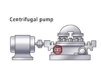
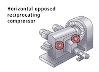
Robertshaw Vibration Instruments can be used on rotating or reciprocating machines. To select the proper instrument for your machine, follow the link to Selection Guide Matrix and/or follow the steps below.
  1. Select the unit that meets the environmental conditions that your machine is located in [hazardous area (explosion-proof or I.S.) or non-hazardous; temperature range].
  2. Select the power supply and/or remote reset voltage required.
  3. Select the unit that provides you with the required measurement type, range and frequency for your machine. The type would be acceleration (G's) or velocity (IPS). The range would be the G range or IPS range. The frequency would be in Hertz (RPM of machine ÷ 60).
  4. If you require time delays (Start, Monitor or Start & Monitor delays – see note below), select the instrument that offers that feature. Models 375A/376A series offer fixed time delays; Model 566 offers adjustable Monitor Delay; Model 563A MUST BE used with Vibraswitch Model 366 or 365, and provides adjustable time delay for the units that are connected to the 563A Monitor. If time delay is not required proceed to step 5 below.
  5. Select the function that you desire:
    1. Alarm or shut down only by:
      1. Electrical SPDT or DPDT Switch Operation (Models 365/366, Models 375A/376A with Start Delay Only).
      2. Solid State Triac Switch Operation (Models 375A/376A except for Start Delay ONLY Model which has SPDT Switch Contacts).
      3. Pneumatic Operation (Model 368).
    2. 4-20 mADC output only (Models 570B/571A).
    3. 4-20 mADC output with alarm and/or shut down contacts, triac outputs (Model 566).
  6. Check to see if the Model selected above has a mounting configuration suitable for your application. All units are surface mount except for the following:
    1. Models 570B/571A are stud mount.
    2. Model 563A Monitor is used with the surface mount 365/366 Vibraswitches to provide adjustable start and monitor time delays.
  7. After you have made your selection, review the complete Product Specification Sheet to verify your selection is correct.

    NOTE:
    Start, Monitor, or Start & Monitor Delays are used to prevent unwanted shut down or alarm during start-up or normal operation of your machine.
    1. Start Delay: Prevents unwanted shut down when excessive vibration exists (which exceeds the set-point of the vibration switch or monitor) during the start-up of the machine.
    2. Monitor Delay: Prevents unwanted shut down when short excessive vibration spikes occur (which exceed the set-point of the vibration switch or monitor) during normal operation of the machine. Spikes are typically caused by detonation, cavitation, other machinery in the immediate area, etc.
The 365A and 366 Vibraswitch malfunction detectors provide maximum protection for large motors, pumps, compressors and other rotating or reciprocating equipment by responding to mechanical malfunctions the instant they occur. The 365A is UL and c-UL certified Explosion-proof, and Type 4/4X & IP66 Weatherproof, E365A is ATEX certified,. The 366 is NEMA 4 and CSA certified.

The 375A and 376A Vibraswitches are identical to the 365/366 models, except that they incorporate built-in electronic starting, monitoring or combination starting and monitoring time delay circuits. The 375A is FM approved. The 376A has a NEMA 4 enclosure. Both require 120 VAC power.

The EURO366G Vibraswitch malfunction detector provides maximum protection from rotating and reciprocating of large motors, pumps or compressors. It is intended for indoor or outdoor use in hazardous or non-hazardous areas with ATEX and CE certifications.

The 368 pneumatically operated Vibraswitch constitutes the most effective known method of avoiding costly damage due to mechanical malfunction of rotating and reciprocating machinery where air is the operating control medium.

The 566 velocity acceleration vibration monitor employs totally solid state circuitry. Sensing mode, whether velocity or acceleration, is field selectable without loss of accuracy.

The 570B loop-powered, stud mount, vibration transmitter provides a 4-20 mADC output proportionate to vibration. This unit, known for its compact size, has a two-pin connector that mates with a splash-proof connector/cable assembly.

The 571A loop-powered, stud mount, vibration transmitter provides a 4-20 mADC output proportionate to vibration. This unit measures acceleration or velocity in three different ranges and is reverse polarity protected. It is compact in size and a 1/4-28 tapped hole and stud are provided for mounting. The two-pin connector mates with a standard MIL-C-5015 two-socket connector with a boot that provides weatherproof and splash-proof connection.


Saturday, May 16, 2009

GFCI ~ manual reset vs. automatic reset

trc gfci 30 amp
Ground Fault Circuit Interrupter or a GFCI is a switch designed to protect people from electrical shocks and electrocution.  The GFCI monitors the current flow into and out of an appliance or circuit and if the current is not equal, the GFCI will switch or trip in milliseconds.  After a trip the GFCI needs to be reset by pushing the "reset" button on the GFCI.  GFIC's are  required in homes in the bathrooms, kitchens and laundry rooms.  

A GFCI can come in wither manual reset mode or automatic reset models.  In this discussion regarding auto vs. manual reset is not after a GFCI trips due to a fault, but when the GFCI's circuit loses power or is initially powered up or plugged in.  GFCI's in homes that are wired into the wall are all AUTO reset GFCI's.  The GFCI after a power outage will reset itself with an electrical coil so that it is "ready" to go.  An auto reset GFCI should always be used for indoor use when the load is not a dangerous.  

A manual reset GFCI is usually used for outdoor power equipment or on the job site electrical tools and applications.The manual reset GFCI will need to be "reset" when the GFCI is plugged in or when power is applied to the curcuit.  The GFCI will trip when power is removed from the circuit or unplugged.  The GFCI will also trip when a fault is detected.  In both cases the GFCI will need to be manually reset.  Most of the GFCI's that we sell are manual reset GFCI's.


Thursday, May 14, 2009

GFCI ~ Ground Fault Circuit Interrupter

A "GFCI" is a ground fault circuit interrupter. A ground fault circuit interrupter is an inexpensive electrical device that, if installed in household branch circuits, could prevent over two-thirds of the approximately 300 electrocutions still occurring each year in and around the home. Installation of the device could also prevent thousands of burn and electric shock injuries each year.

The GFCI is designed to protect people from severe or fatal electric shocks Because a GFCI detects ground faults, it can also prevent some electrical fires and reduce the severity of others by interrupting the flow of electric current.

In the home's or other building's wiring system, the GFCI constantly monitors electricity flowing in a circuit, to sense any loss of current. If the current flowing through the circuit differs by a small amount from that returning, the GFCI quickly switches off power to that circuit. The GFCI interrupts power faster than a blink of an eye to prevent a lethal dose of electricity. You may receive a painful shock, but you should not be electrocuted or receive a serious shock injury.

In homes built to comply with the National Electrical Code (the Code), GFCI protection is required for most outdoor receptacles (since 1973), bathroom receptacle circuits (since 1975), garage wall outlets (since 1978), kitchen receptacles (since 1987), and all receptacles in crawl spaces and unfinished basements (since 1990).

Owners of homes that do not have GFCls installed in all those critical areas specified in the latest version of the Code should consider having them installed. For broad protection, GFCI circuit breakers may be added in many panels of older homes to replace ordinary circuit breaker. For homes protected by fuses, you are limited to receptacle or portable-type GFCIs and these may be installed in areas of greatest exposure, such as the bathroom, kitchen, basement, garage, and outdoor circuits.

A GFCI should be used whenever operating electrically powered garden equipment (mower, hedge trimmer, edger, etc.). Consumers can obtain similar protection by using GFCIs with electric tools (drills, saws, sanders, etc.) for do-it-yourself work in and around the house.

Circuit breaker and receptacle-type GFCIs may be installed in your home by a qualified electrician. Receptacle-type GFCIs may be installed by knowledgeable consumers familiar with electrical wiring practices who also follow the instructions accompanying the device. When in doubt about the proper procedure, contact a qualified electrician. Do not attempt to install it yourself.

The portable GFCI requires no special knowledge or equipment to install.

All GFCIs should be tested once a month to make sure they are working properly and are protecting you from fatal shock. GFCIs should be tested after installation to make sure they are working properly and protecting the circuit.

To test the receptacle GFCI, first plug a nightlight or lamp into the outlet. The light should be on Then, press the "TEST" button on the GFCI. The GFCI's "RESET" button should pop out, and the light should go out.

If the "RESET" button pops out but the light does not go out, the GFCI has been improperly wired. Contact an electrician to correct the wiring errors.

If the "RESET" button does not pop out, the GFCI is defective and should be replaced. 

If the GFCI is functioning properly, and the lamp goes out, press the "RESET" button to restore power to the outlet.

GFCI's should be used in Commercial and industrial enviroments as well.  NEC code requires the use of GFCI's with all portable electrical tools, that need to be plugged in, within a plant or on a job site.

Related products for commercial properties and job sites are our cable mats.